
Out of TRRS, 6-pin miniDIN, and DE-9, I’ve found 8P8C Modular Connector (“RJ-45”) ends are the simplest to construct, cheapest, and most universal connector for TNCs. Buying a modular connector crimp tool to build TNC interface cables is a good investment for such common connectors. Other special ends can be purchased as pre-made cables and adapters can be paired with simple RJ-45 couplers.
Pinout
The common signalink “straight thru” pinout (RJ-45) [Credit: Masters Communications] is a good choice for interoperability.
Pinout shown as you are looking into the open end of the RJ-45 female socket. Orientation is contact pins are up and the locking tab slot is down.
The pinout follows standard EIA Ethernet numbering.
 12345678
 ________
|''''''''|
|        |
|__    __|
|__|__|__|
- 1 = RX Audio
- 2 = TX Audio
- 3 = PTT
- 4 = COS - Not normally used
- 5 = CTCSS - Not normally used
- 6 = Ground
- 7 = Ground
- 8 = Ground
“RX Audio” corresponds to the speaker / packet output of the radio and the mic/line input of the soundcard.
“TX Audio” corresponds to the microphone / data in of the radio and the output of the soundcard.
The other end of the cable is radio-dependent. Typically, I will cut cables with special connectors and recrimp the other ends with RJ-45: simple, high-quality connections without soldering.
6-pin MiniDIN
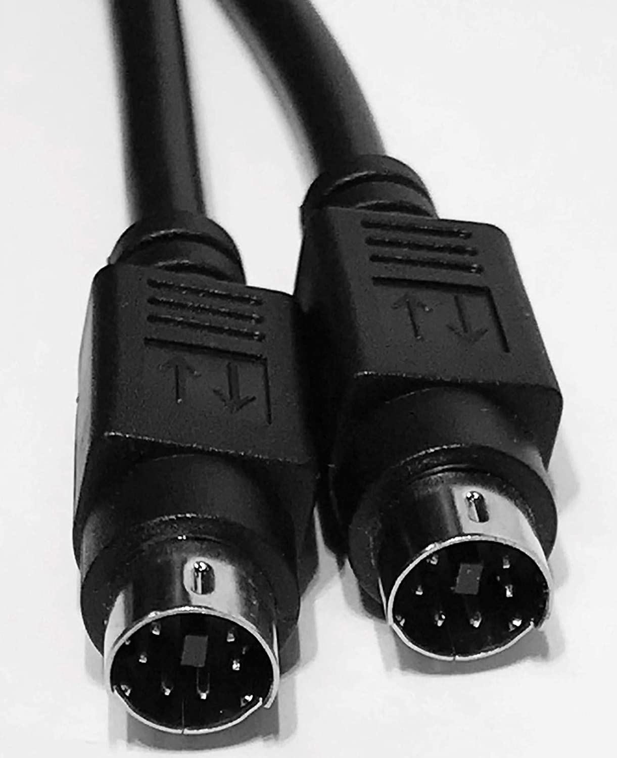
Commonly known as a PS/2 connector, found on many keyboard and mice from the 90s and 2000s. Maybe these connectors can be pillaged from an old piece of hardware? But some may be missing wires for certain pins. A “data” cable is a sure bet, and can be used to build 2 TNC cables.
Below is the most common pinout that I’ve encountered with this connector. There is no standard wire coloring, but I’ve found cables of the same brand/batch to be consistent. Always better to check with a meter and then double check.
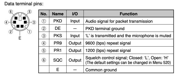
Diagram snipped from the Kenwood TM-V71a Manual [PDF]
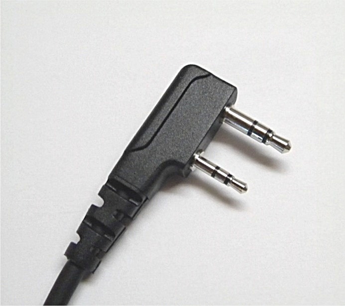
2-Prong K-Style connector
This seems like the most common connector type on handheld radios, particularly from China, so it’s nice to have a few of these on hand for quick testing.
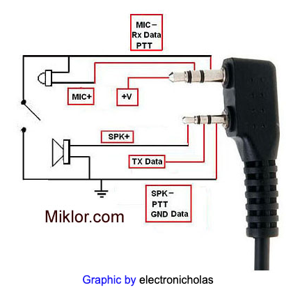
Miklor provides an info page with excellent diagrams of the plug pinout (one of which is reproduced here).
Remember: ferrite chokes can be added to USB and Audio cables to reduce RFI and improve performance, particularly when the transmitter and antenna may be in close proximity to the node.
Signalink SLCABHTW
Unfortunately, the SLCABHTW isn’t wired straight through, so it can’t be directly used with the DRA-34 or a generically wired Signalink. I’m not exactly sure why Tigertronics manufactures the RJ-45 modular end with a multitude of different pinouts, and relies on “jumpering” for compatibility, but it sure makes it harder to reuse one soundcard with different radios.
Thankfully, it’s easy enough to lop the end off and make it right! Using the included jumper sheet, one can even infer the correct wires without a meter.
- 1 = RX Audio Green (SPKR 5)
- 2 = TX Audio Red (MIC 1)
- 3 = PTT Light Blue (PTT 3)
- 4 = Empty
- 5 = Empty
- 6 = Ground Black (G 2)
Other wires that I cut off to avoid shorts:
- White - Ring 2.5mm - TX Data
- Orange - Tip 3.5mm - V+
3.5mm + 2.5mm phono
I went looking for K-type connector ends (for repairing speaker mics) and found quite a few on ebay that would take a long time to ship. Alternatively, it’s easy to find separate 3.5mm and 2.5mm stereo phono ends or “headphone” cords that go from 2.5mm to 3.5mm and can be cut in half and recombined with a modular plug to make a homebrew connector.
The connectors I bought on amazon pin out with following colors:
3.5mm
- Tip (+V): red (cut)
- Ring (Mic TX Audio): white
- Shield (PTT): black
2.5mm
- Tip (Speaker RX Audio): red
- Ring (DATA): white (cut)
- Shield (PTT): black
RJ45
- 1 = RX Audio - 2.5 Tip Red
- 2 = TX Audio - 3.5 Ring White
- 3 = PTT - 3.5 Shield Black
- 6 = Ground - 2.5 Shield Black
4-conductor speakermic leads to RJ45
- 1 = RX Audio - 2.5 Tip Green
- 2 = TX Audio - 3.5 Ring Red
- 3 = PTT - 3.5 Shield Black
- 6 = Ground - 2.5 Shield White
Kenwood RJ-45
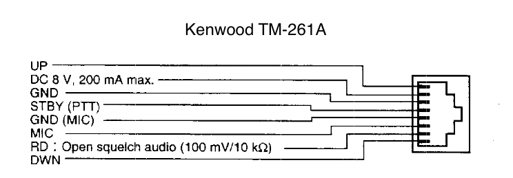
Although missing from the modern variant, TM-281A, the previous model, the TM-261A actually has an RD (Read Data?) pin on the microphone jack, which can be used to get pre-squelch packet audio. This is very convenient as it retains the internal speaker functionality for monitoring.
- 1 = RX Audio - KW Pin 2 Yellow
- 2 = TX Audio - KW Pin 3 Red
- 3 = PTT - KW Pin 5 Orange
- 6 = Ground - KW Pin 4 Black
- 7 = Ground - KW Pin 6 Grey
Yaesu 10-pin
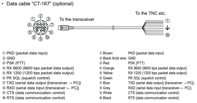
Image snipped from FTM-400XDR_DE_OM_ENG_EH034M210_1608U-EM-2.pdf
Since the Yaesu internal TNC isn’t exposed via serial or bluetooth our next best bet is to use a soundcard with the standard pinout. Colors given below are from the CT-167 cable, but you can find a similar connector ends for $5 on ebay (although I cannot vouch for their quality)
- 1 = RX Audio - Orange, pin 4
- 2 = TX Audio - Brown, pin 1
- 3 = PTT - Red, pin 3
- 4 = COS - Green, pin 6
- 6 = Ground - black, thick
Cut Yellow, Blue, Grey, White, Black
Alinco DB-9
The DB-9 is another common connector, which can often be pilfered from an existing unused cable. Alternatively, DB-9 male-to-male jumpers are cheap and easy to source.
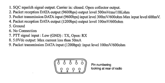
Image taken from p. 41 of the DR-135T mkIII manual [PDF].
- 1 = RX Audio - pin 2 LIGHT RED (9600 baud)
- 2 = TX Audio - pin 3 DARK RED (9600 baud)
- 3 = PTT - pin 7 DARK BLUE (shiney)
- 4 = COS - pin 1 BLACK
- 6 = Ground - pin 5 YELLOW
RA-33 Adapter
- 1 = RX Audio - pin 6 ORANGE
- 2 = TX Audio - pin 2 LIGHT RED
- 3 = PTT - pin 5 YELLOW
- 4 = COS - pin 3 DARK RED (leave disconnected for non-AllStar use)
- 6 = Ground - pin 8 DULL BLUE
Direct GPIO Adapter
This adapter uses a USB sound card + GPIO pins available on a Raspberry Pi to key PTT. To avoid damage to the Pi itself, a transistor and resistor will be used to avoid hitting the pin with 5v directly.
For PTT purposes, I recommend RPi pin 16 (GPIO 23) or 18 (GPIO 24) with easily accessible ground pin on either side. In the examples, I’ll be using pin 18.
Until a schematic can be posted, the circuit is essentially a PN2222 NPN transistor with
- radio PTT line on the collector pin
- raspi GPIO through a 100k resistor on the base pin
- ground on the emitter pin
When the GPIO is pulled high, it switches the transistor ON, and PTT is activated.